Sensors & outputs Trigger
Opel CDI crank
Crank angle sensor · sensor · Trigger
Opel CDI / CDTI crank sensors are a trigger pickup, usually a three-wire Hall, sometimes a two-wire VR depending on the engine code. This page does not assign device pin letters. Those letters are not confirmed for the sensor sold as the Opel CDI crank. Race Core landings below are the published Hall and VR inputs. Meter the part, then write the letters on the lid.
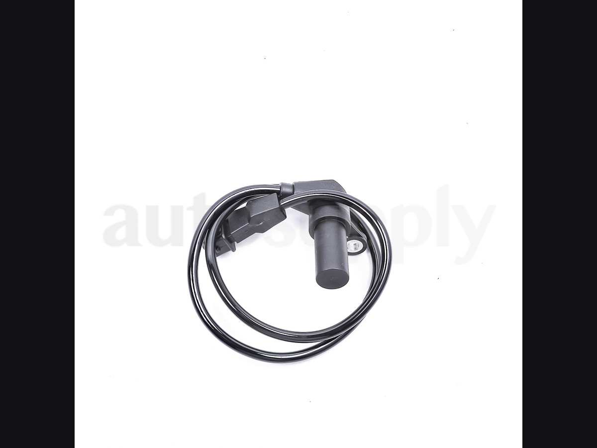
Typical parts: Opel CDI crank / CAS as used on the standalone harness. Engine-code specific. Confirm Hall versus VR before you crimp.
Warning — Draft. Public Opel diesel diagrams name a crank signal and a low reference, and often a 5 V supply on Hall cam sensors in the same loom. They do not publish one cavity order that covers every CDI crank plug. Do not copy a pin chart from a different engine onto this connector.
Device pinout
Looking into the connector, locking tab at the top. The three cavities are drawn so you can mark them after you meter. They are not a claimed OEM order.
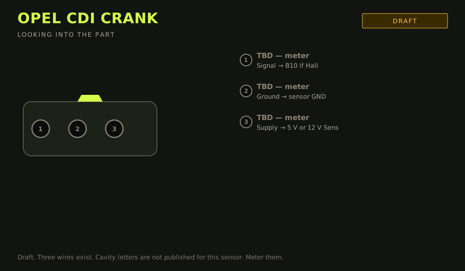
- Connector: 3-way on the sensor. Cavity letters are not published for this part.
- Layout (looking into the part): three cavities; polarising key top
| Device pin | Function | Type | Race Core | TunerStudio |
|---|---|---|---|---|
| TBD | Signal, if the sensor is Hall | Signal | B10 | Digital 1 |
| TBD | Sensor ground | Ground | C1–C8 / C29 / C31 | Sensor GND |
| TBD | Supply, 5 V or 12 V | 5 V | C9 / C21 / C32, or C11 / C23 | 5 V Sens 1 or 12 V Sens |
| Pair | VR+ / VR−, if the sensor is a coil | Signal | B5 / B13 | VR 1+ / VR 1− |
Wiring notes
- Key-on, unplugged at the sensor end of your harness: one pin near 5 V or 12 V, one pin at sensor ground, one pin open. The open pin is the signal on a Hall part. Land that on Digital 1 (B10). Pull-up on.
- If two pins read a few hundred ohms and the third is the screen, it is a VR sensor. Use VR 1 (B5 / B13), not Digital 1. Shield to sensor ground at the ECU only.
- A 12 V Hall sensor does not belong on 5 V Sens, and a 5 V Hall sensor does not belong on 12 V Sens. The datasheet or the key-on voltage decides. If you cannot tell, stop.
- Core EFI V4 and Micro Core cavity numbers are TBD. The B and C pins above are Race Core F7.
- This is not the Opel optical distributor CAS used on some petrol engines. A four-wire optical CAS is a different part.
Failure modes
- RPM 0 with a Hall sensor: supply and signal swapped, or the pull-up is off.
- RPM in the thousands: a VR sensor landed on Digital 1, so both halves of each tooth count.
- Signal dies hot: the sensor, not the decoder. Offset will not bring it back.