Sensors & outputs Trigger
Crank Hall
3-wire CKP, LS 24x / 58x · sensor · Trigger
Open-collector or internally-conditioned Hall. Three wires: supply, ground, signal. LS Gen III 24x is a VR with on-sensor conditioning — treat it as Hall, falling edge, pull-up on.
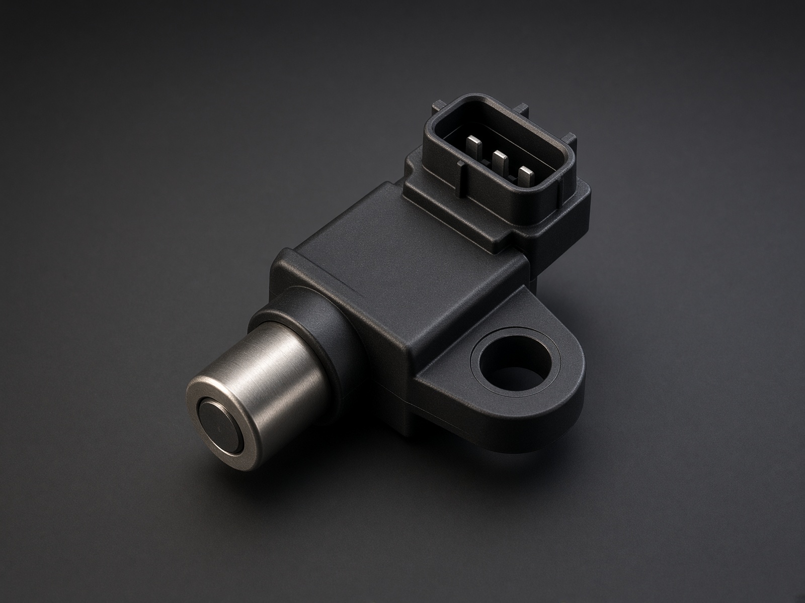
Typical parts: GM LS Gen III black 24x (above starter); GM LS Gen IV grey 58x; Honeywell Hall 3-wire
Warning — GM swapped the letters. The application note for the engine you are on wins. If RPM is 0 or 12,000, you have supply and signal swapped — not a decoder problem.
Device pinout
Looking into the sensor, locking tab at the top. Meter 12 V / ground / signal — do not trust a colour chart.
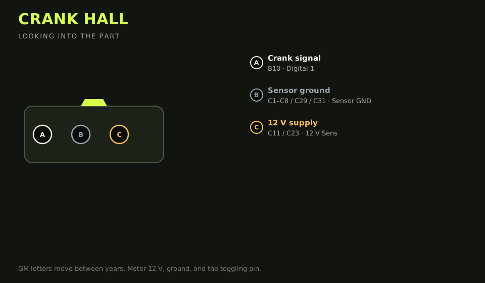
- Connector: GM 3-way on the sensor. Letters are stamped; GM has swapped them across years.
- Layout (looking into the part): A · B · C; polarising key top
| Device pin | Function | Type | Race Core | TunerStudio |
|---|---|---|---|---|
| A | Crank signal (common LS Gen III) | Signal | B10 | Digital 1 |
| B | Sensor ground | Ground | C1–C8 / C29 / C31 | Sensor GND |
| C | 12 V supply | 12 V | C11 / C23 | 12 V Sens |
Wiring notes
- The table is the usual Gen III black sensor: A signal, B ground, C 12 V. Some GM 24x parts are A = 12 V, B = signal, C = ground. Key-on: one pin is 12 V, one is ground, one toggles while cranking.
- TunerStudio: Hall, pull-up on. LS 24x uses the falling edge — the rising edge is unique-timed and will not decode.
- Gen III sensors are black. A grey Gen IV 58x sensor on a 24x reluctor is the wrong part.
- 5 V Hall sensors exist (many European). Use 5 V Sens 1 instead of 12 V Sens and confirm the datasheet.
- Do not land Hall ground on a power-ground stud.
Failure modes
- RPM 0: supply and signal are swapped, or the pull-up is off.
- RPM in the thousands on an LS 24x: the rising edge is selected. Gen III 24x decodes on the falling edge.
- A grey Gen IV 58x sensor on a black-sensor 24x reluctor: wrong part. The decoder will not save it.
- Signal collapses when the headlights or fan come on: the ground is a power-ground stud.