Sensors & outputs Trigger
Cam Hall
CMP, half-moon / 1x / 4x · sensor · Trigger
Same 3-wire family as crank Hall. Default cam is Digital 2. Exhaust / cam 2 is Digital 6. Sequential injection and COP need this pulse.
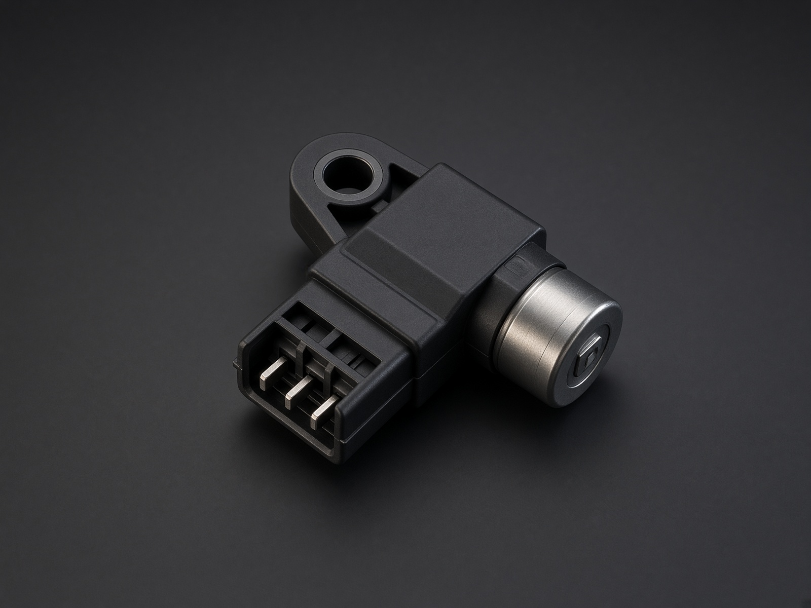
Typical parts: GM LS half-moon cam Hall; Toyota 3-tooth cam Hall; Nissan VQ cam Hall
Device pinout
Looking into the sensor, locking tab at the top. Same meter rule as crank Hall.
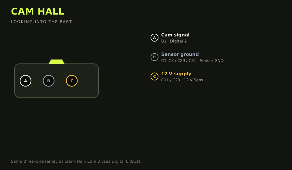
- Connector: 3-way on the sensor
- Layout (looking into the part): A · B · C; polarising key top
| Device pin | Function | Type | Race Core | TunerStudio |
|---|---|---|---|---|
| A | Cam signal | Signal | B1 | Digital 2 |
| B | Sensor ground | Ground | C1–C8 / C29 / C31 | Sensor GND |
| C | 12 V supply | 12 V | C11 / C23 | 12 V Sens |
Wiring notes
- LS Gen III half-moon is at the back of the valley. One pulse per two crank revolutions.
- Cam 2 / exhaust Hall lands on Digital 6 (B11) with the same 12 V and sensor ground.
- A VR cam uses VR 2, not this page.
- One pulse per crank revolution is a wasted-spark cam or a crank sensor on the cam input.
Failure modes
- Crank syncs, sequential fuel does not: cam is missing, or it pulses once per crank revolution (that is a crank pattern on the cam input).
- Cam and crank edges sit on top of each other in the log: the two sensors are sharing a wire.
- One bank of VVT never schedules: cam 2 was left on Digital 2. Exhaust / cam 2 is Digital 6 (B11).