Sensors & outputs Ignition
Coil — IGN-1A
AEM / IGN-1A smart coil · output · Ignition
High-energy 5-pin logic coil. Same 5 V trigger as D585, plus dedicated head and battery grounds. Dwell is shorter than a truck coil at the same spark energy — follow the dwell chart, 40 % duty max.
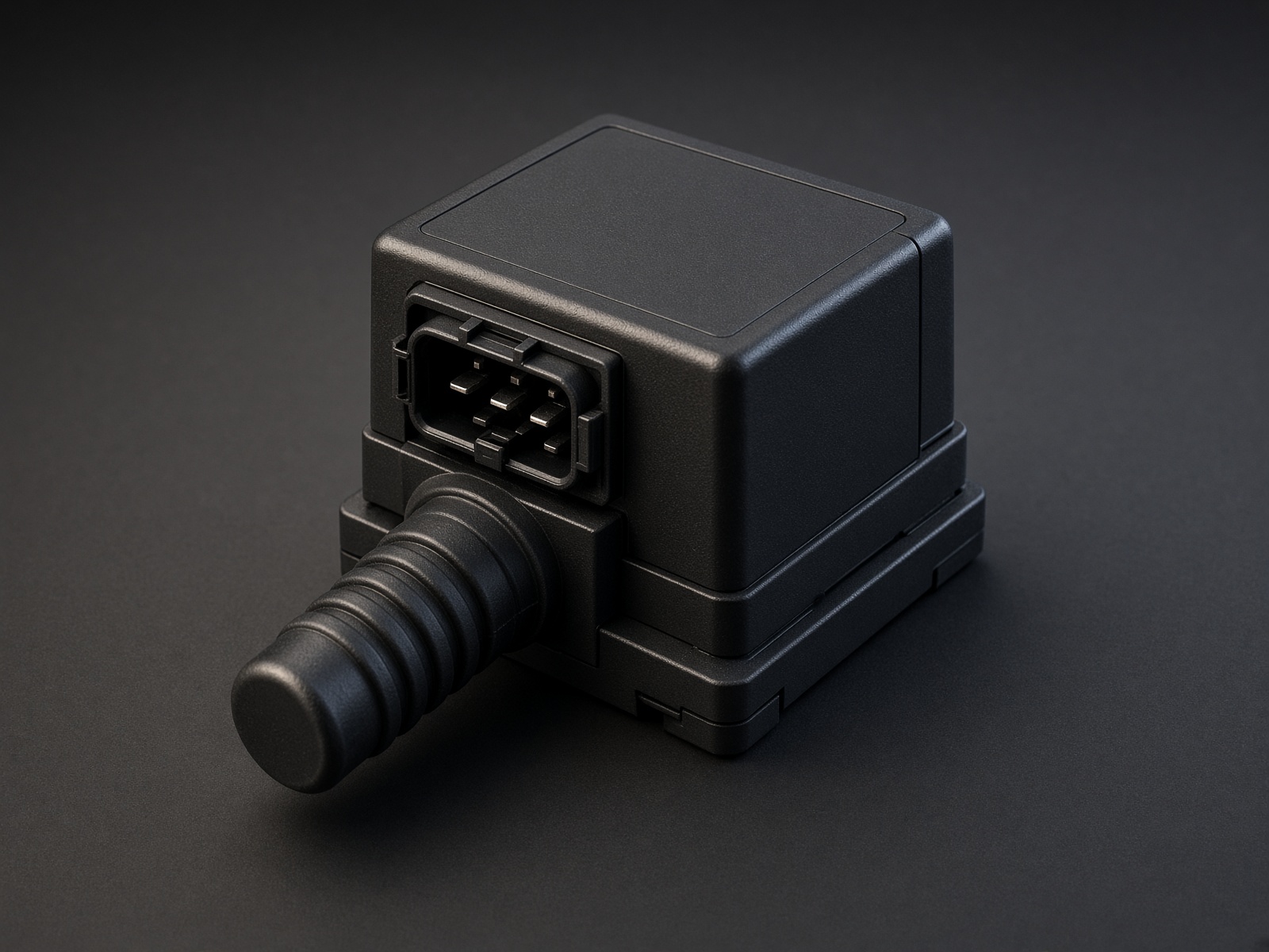
Typical parts: AEM IGN-1A; IGnite IGN-1A clone (confirm pin letters)
Warning — Pin C is mandatory. No head ground on C and the coil will not make full energy. The boot sitting on the plug is not a ground.
Device pinout
Looking into the coil. Pins A · B · C · D · E as stamped.
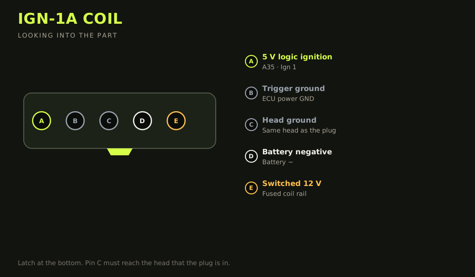
- Connector: 5-way on the coil (Metri-Pack / supplied connector)
- Layout (looking into the part): A · B · C · D · E; polarising key bottom
| Device pin | Function | Type | Race Core | TunerStudio |
|---|---|---|---|---|
| A | ECU trigger 5 V (cyl 1 shown) | Ignition | A35 | Ign 1 |
| B | Trigger ground (ECU power ground) | Ground | A17 / A18 / A24 family | Power GND |
| C | Cylinder-head ground | Ground | Same head as the plug | — |
| D | Battery negative | Ground | Battery − / block strap | — |
| E | Switched 12 V | 12 V | Fused coil 12 V rail | — |
Wiring notes
- Pin B is ECU power ground potential, not sensor ground. Pin C is the head that coil sits on (or the rotor housing, rotary).
- Pins D and E carry peak current. Short, fat wire. A 5 m run of 22 AWG will brown-out the coil at high dwell.
- Same Ign n cylinder-number order as D585.
- Do not dwell past the chart. A hot IGN-1A is a coil that is about to take an ignition pin with it.
Failure modes
- Spark energy collapses under load: pin C is not on the head, or pin D is a long thin wire back to the battery.
- No trigger: pin B was landed on sensor ground instead of ECU power ground, or the logic wire is on a low-side.
- A coil that smells hot: dwell past the chart. It will take the ignition pin with it.