DStage AFR
Wideband controller · sensor · AFR
The DStage controller runs the Bosch LSU heater and pump cell, then offers a 0–5 V wideband voltage and a simulated narrowband. Race Core reads the analog voltage on Analog Volt 5. The six LSU wires stop at the controller.
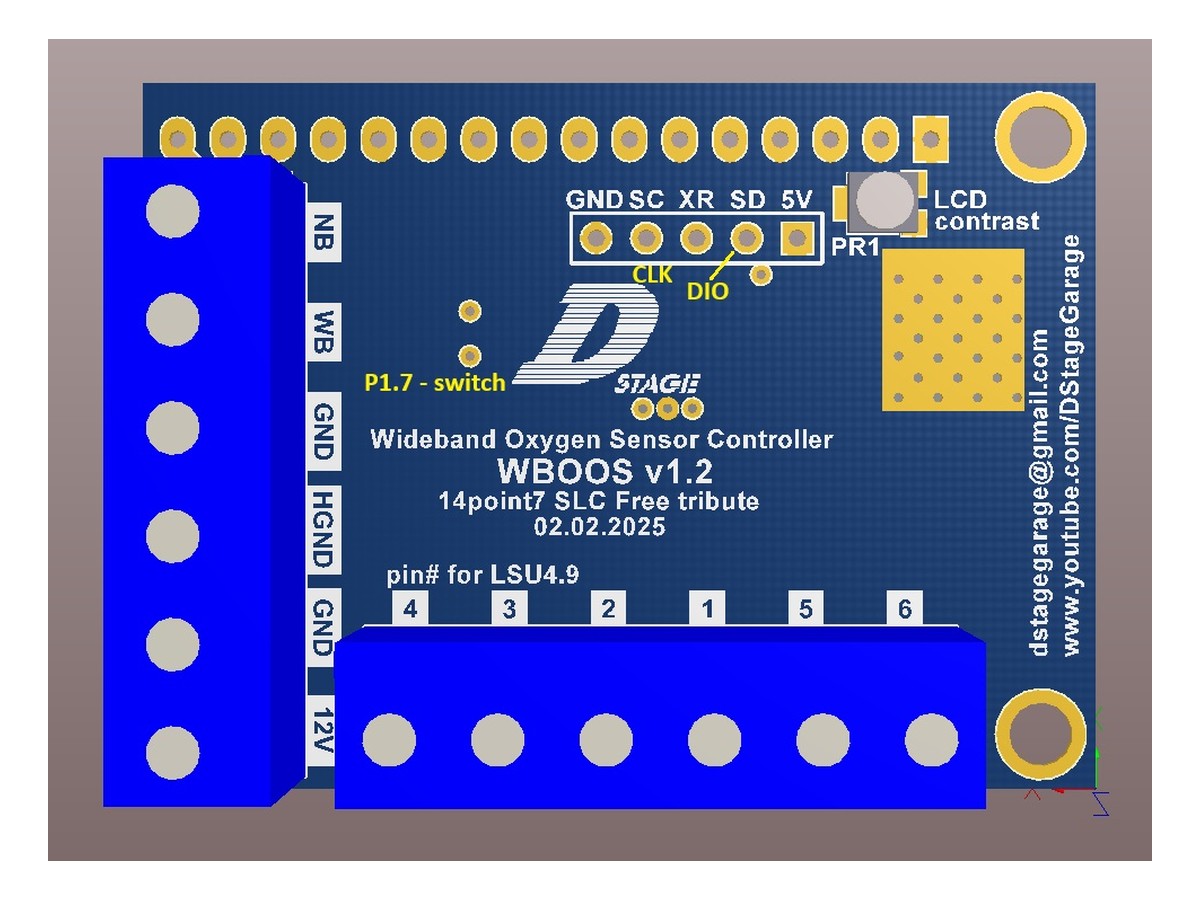
Typical parts: DStage AFR controller as sold for Bosch LSU; probe Bosch LSU 4.9 (0 258 017 025 family)
Warning — Controller pin numbers are not published here. Use the labels on the harness you received. This page only fixes the Race Core end. A guessed cavity on the controller can put 12 V on the analog output.
Device pinout
The controller is a box with a harness, not a sensor you look into. Match the printed labels. The LSU connector itself is on the wideband page.
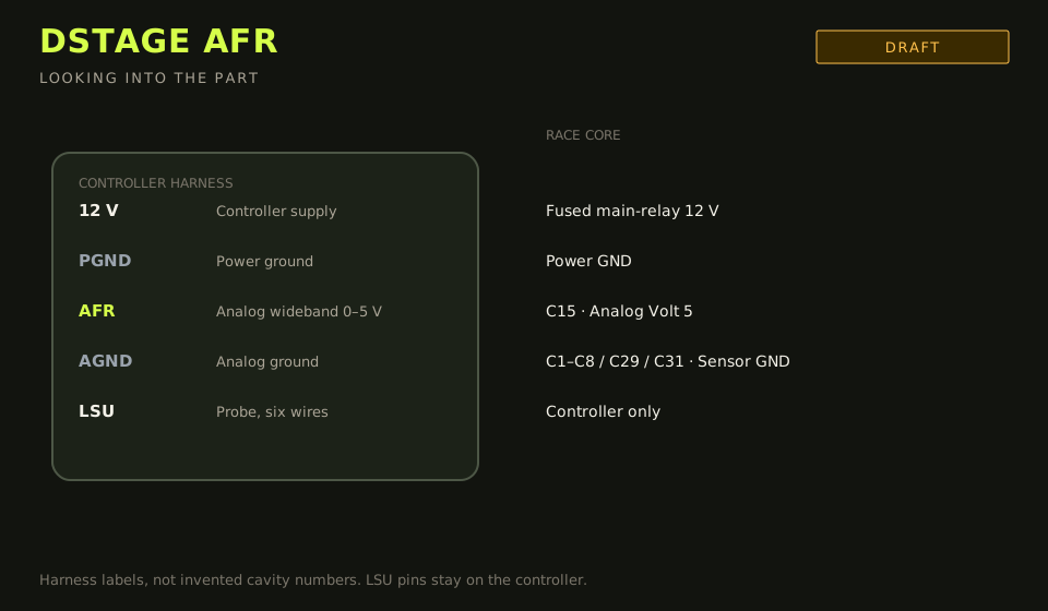
- Connector: harness labels on the controller. LSU connector is on the probe.
- Layout: label on the wire, not a guessed cavity number
| Device pin | Function | Type | Race Core | TunerStudio |
|---|---|---|---|---|
| 12 V | Controller supply | 12 V | Fused main-relay output | — |
| PGND | Power ground | Ground | Power GND | Power GND |
| AFR | Analog wideband 0–5 V | Signal | C15 | Analog Volt 5 |
| AGND | Analog ground | Ground | C1–C8 / C29 / C31 | Sensor GND |
| LSU | Probe, six wires | Signal | Controller only | — |
| NB | Simulated narrowband | Signal | Do not use as the AFR input | — |
Wiring notes
- Set the same 0–5 V scale in TunerStudio that the controller actually outputs. If the ends are undocumented on your unit, log the voltage in free air and at a known idle AFR, then enter those two points. Do not assume another brand’s 10–20 AFR scale.
- Heater current is several amps cold. Fuse the controller 12 V at 5–10 A on the main-relay output. Do not feed it from 12 V Sens.
- CAN is not the default path for this controller. If a later harness brings CAN H/L, those land on B17 / B16 (CAN 1) at 1 Mbit/s, and the analog wire can come off C15. Until that harness is in your hand, use the analog landing.
- Simulated narrowband is for an OEM ECU that still expects a swinging 0–1 V sensor. Race Core closed loop wants the wideband voltage (or CAN), not the NB pin.
- LSU wire colours and cavity numbers are on the wideband page. Green is the trim resistor. Black is Nernst.
Failure modes
- Analog Volt 5 stuck at 0 V or 5 V while the controller display looks alive: analog ground missing, or the AFR wire is on the NB pin.
- Controller LED never leaves the heat cycle: LSU connector not seated, or heater + (grey) not on fused 12 V.
- AFR swings lean the moment the cooling fan starts: controller ground is sharing a fan or starter path.
- Free-air reads as a rich number: the TunerStudio scale does not match the controller.